Damped Sine |
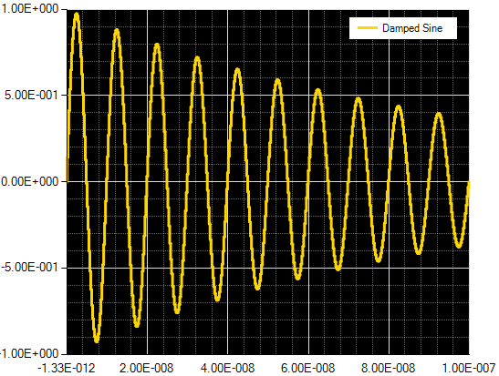
The damped sine waveform is defined by the equation:
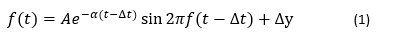
where A is the amplitude, f is the frequency, α is the decaying exponential factor Δt is the time shift, and Δy is the shift along the Y axis.
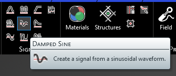
Create a Damped Sine signal selecting the Damped Sine waveform within the signals panel under the EMA3D tab in the ribbon.
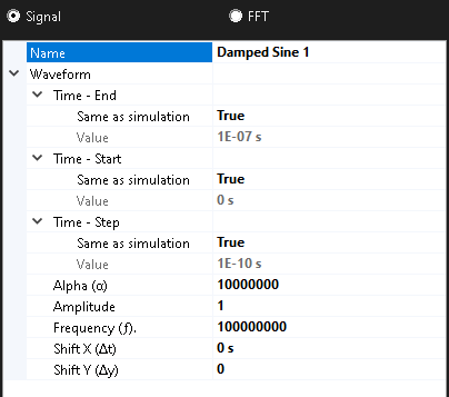
After adding a signal, the signal edit window will appear with a graph of the signal and various parameters that can be adjusted. The signal can be edited immediately or at a later time by right clicking the signal name in the Simulation Tree and selecting edit in the pop-up menu. These parameters are described in the table at the end of this section. Additionally, the frequency spectrum of the signal can be inspected by clicking FFT in the top left of the window.
If you do not wish to edit the signal close out of the signal window using the small x in the top right corner of the window.
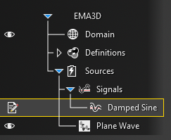
This will place the newly-created signal in the Simulation Tree under Signals within the Sources node.
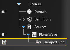
To add the signal to a source, click and hold the signal within the Signals node in the Simulation Tree and then drag and drop it on the source (e.g., on the plane wave). The signal should then be nested beneath the corresponding source.
Entry | Meaning |
|---|---|
Name | The display name of the signal |
Time - End [s] | The simulation time the signal turns off. The default end time matches the simulation end time. Time - End can be changed only if the field Same as simulation is set to False |
Time - Start [s] | The simulation time the signal turns on. The default start time matches the simulation start time. Time - Start can be changed only if the field Same as simulation is set to False |
Time - Step [s] | The sample rate of the signal. The default step time matches the simulation step time. Time - Step can be changed only if the field Same as simulation is set to False |
Alpha (α) | The alpha parameter of the waveform. |
Amplitude (A) | The waveform amplitude |
Frequency (f) [Hz] | The waveform frequency |
Shift X (Δt) [s] | Shift the beginning of the waveform relative to t=0s. This parameter differs from Time - Start. In Time - Start the original signal does not change, it simply waits to turn on until the specified time. In Shift X (Δt), the signal is recalculated using the time specified in Shift X (Δt) as the new t=0s such that in the wave equation t is replaced by (t-Δt), and this signal starts immediately. So, for example, in a damped sine wave, changing Shift X (Δt) to a positive value will cause an increase in the initial amplitude as the entire wave is shifted to the right along the X axis. Note that all signals MUST start at 0 or the EMA3D simulation will provide a warning and fail when run. |
Shift Y (Δy) | Shifts the waveform amplitudes relative to 0. Note that all signals MUST start at 0 or the EMA3D simulation will provide a warning and fail when run. |
Other Resources
EMA3D - © 2026 EMA, Inc. Unauthorized use, distribution, or duplication is prohibited.